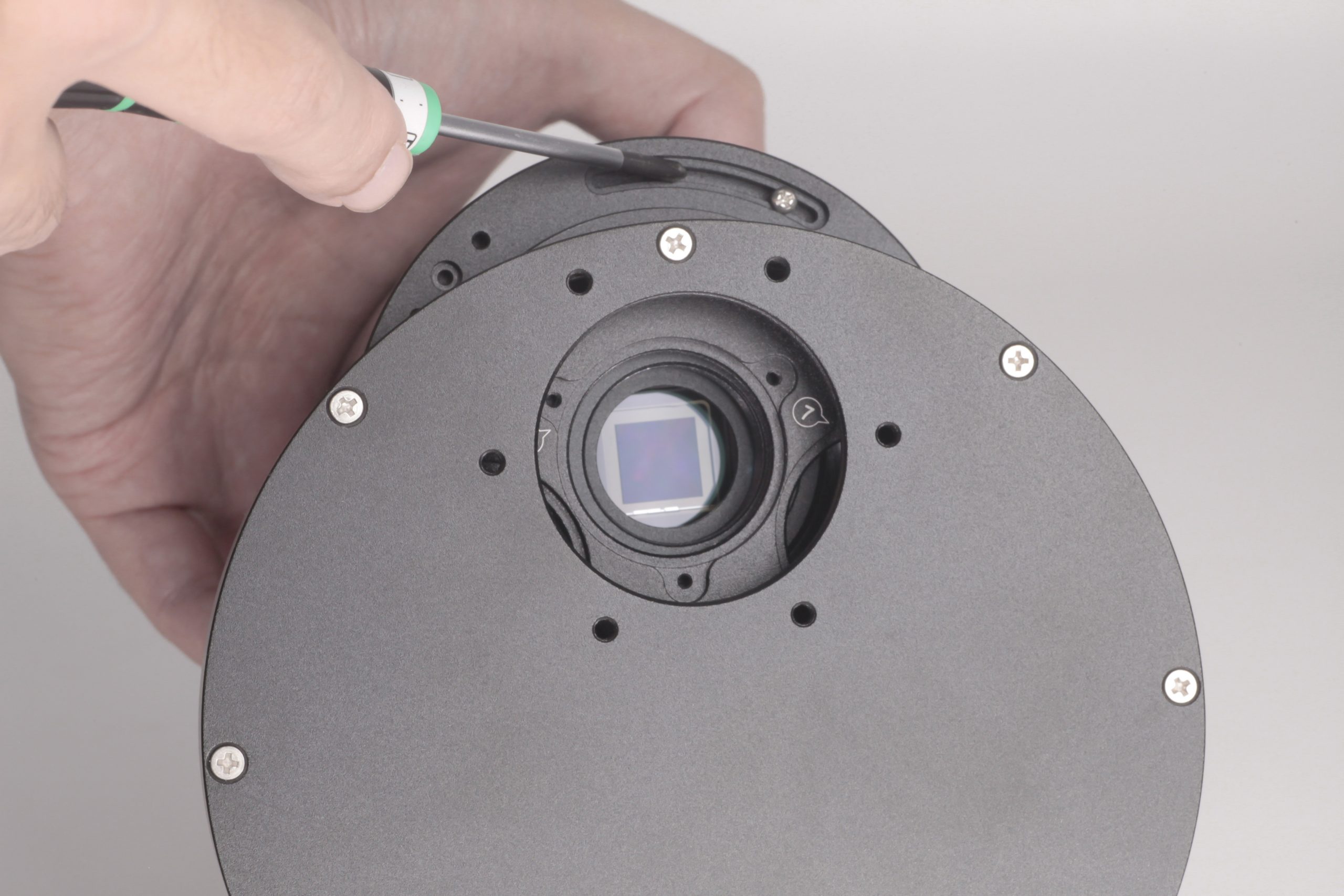
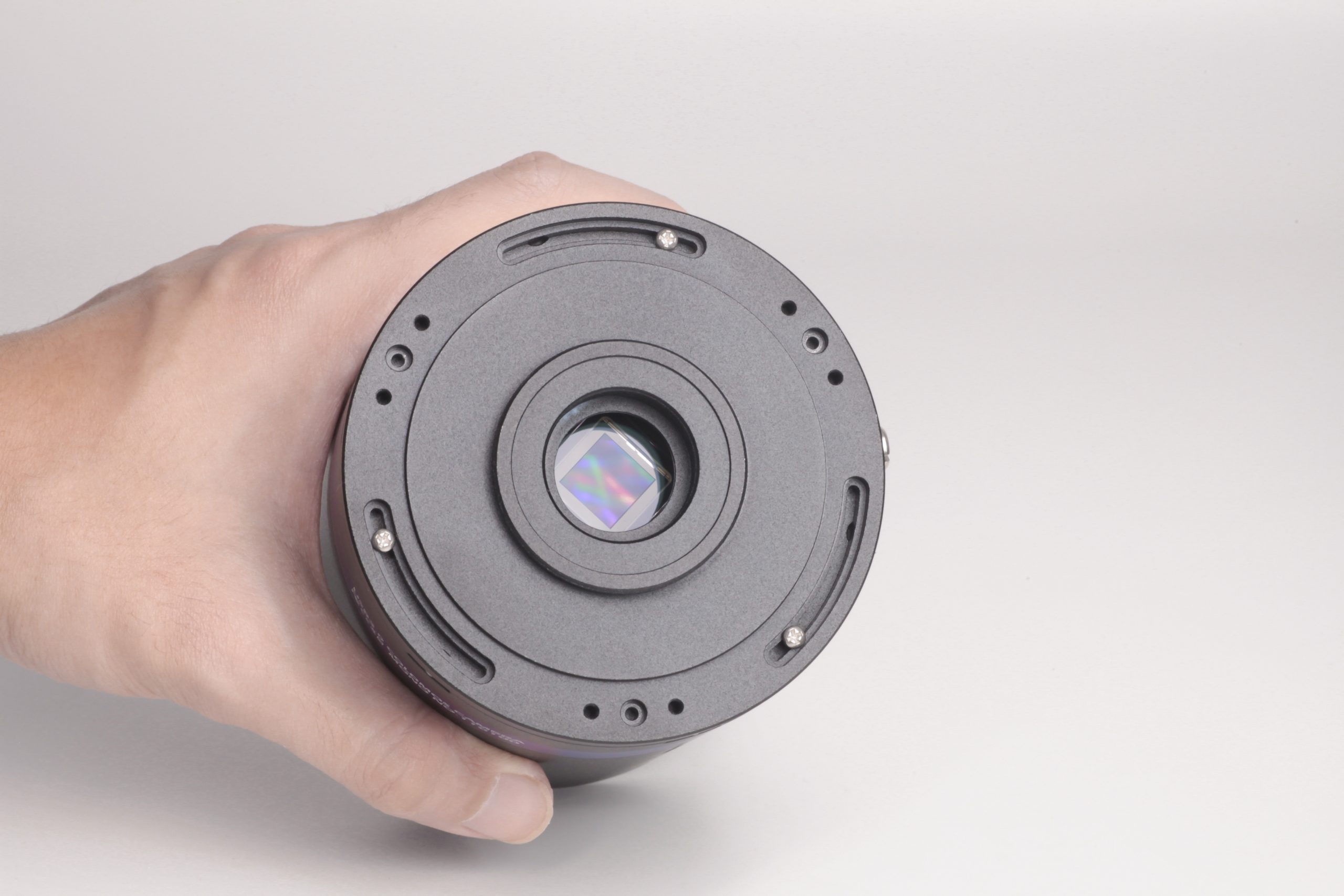
QHYCCD QHY533M+CFW3S_SR
| Availability: | More on the Way to us |
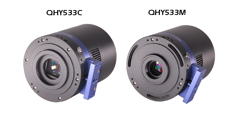
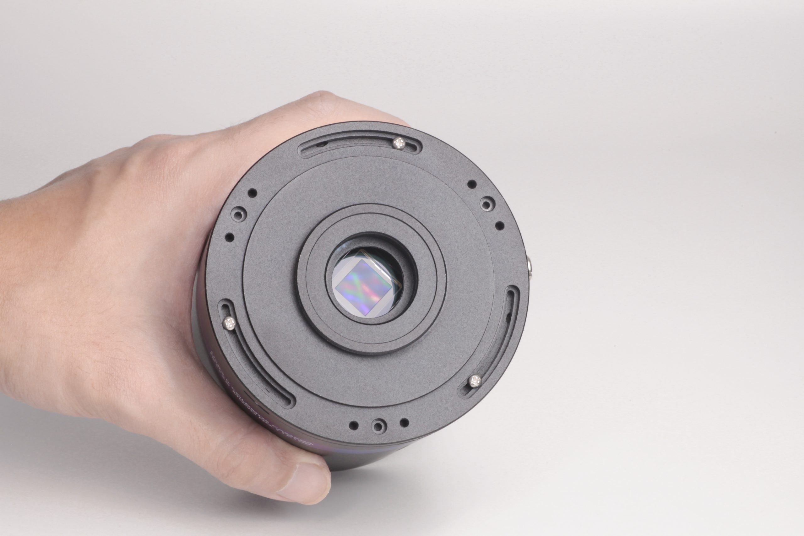
With the advantage of low readout noise and high-speed readout, CMOS technology has revolutionized astronomical imaging. The QHY533M/C is a new generation of back-illuminated CMOS cameras with 3.76um pixels.
One benefit of the back-illuminated CMOS structure is improved full well capacity. This is particularly helpful for sensors with small pixels. In a typical front-illuminated sensor, photons from the target entering the photosensitive layer of the sensor must first pass through the metal wiring that is embedded just above the photosensitive layer. The wiring structure reflects some of the photons and reduces the efficiency of the sensor.
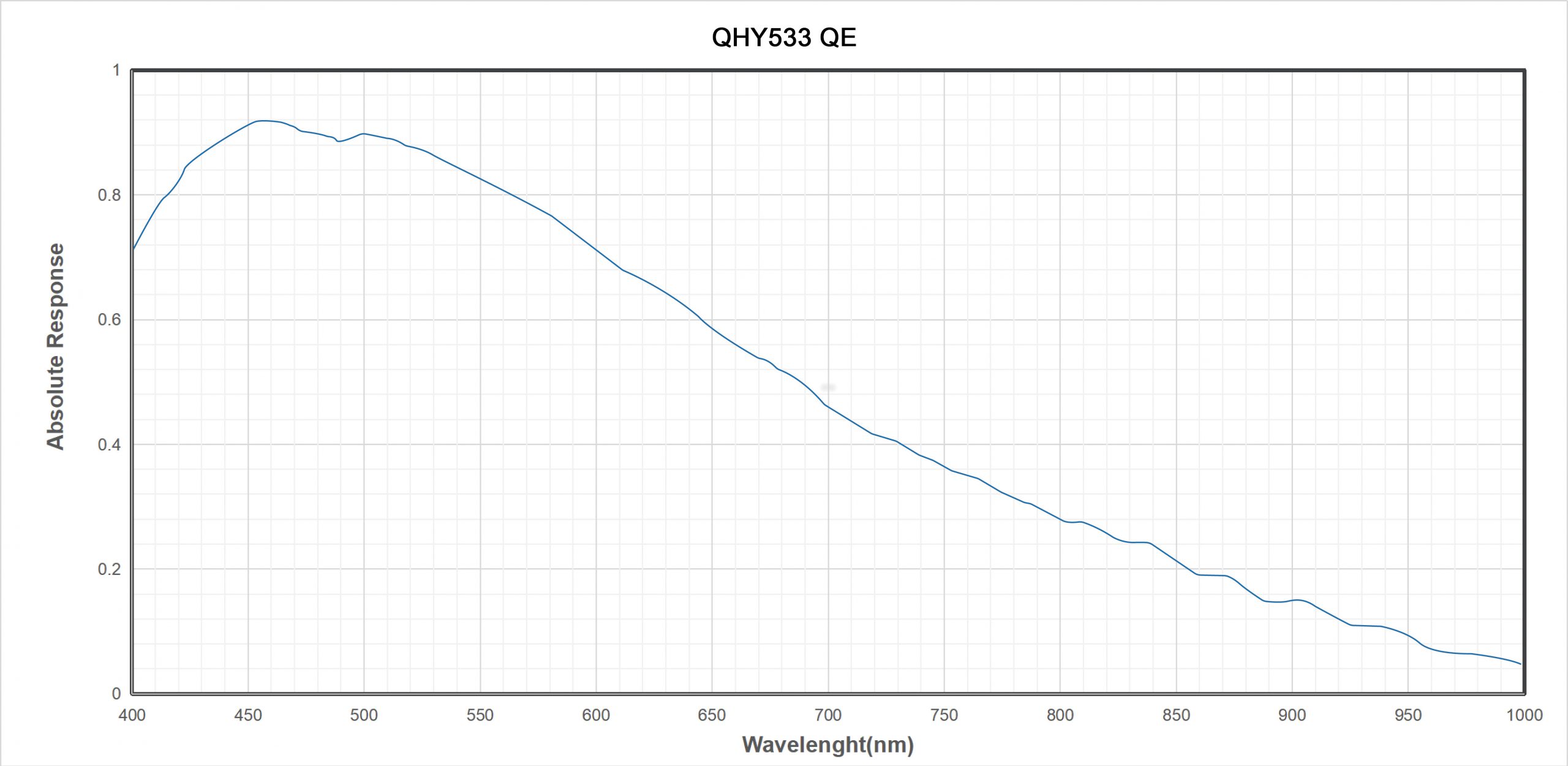
In the back- illuminated sensor the light is allowed to enter the photosensitive surface from the reverse side. In this case the sensor’s embedded wiring structure is below the photosensitive layer. As a result, more incoming photons strike the photosensitive layer and more electrons are generated and captured in the pixel well. This ratio of photon to electron production is called quantum efficiency. The higher the quantum efficiency the more efficient the sensor is at converting photons to electrons and hence the more sensitive the sensor is to capturing an image of something dim.
In the DSLR implementation there is a RAW image output, but typically it is not completely RAW. Some evidence of noise reduction and hot pixel removal is still visible on close inspection. This can have a negative effect on the image for astronomy such as the “star eater” effect. However, QHY Cameras offer TRUE RAW IMAGE OUTPUT and produces an image comprised of the original signal only, thereby maintaining the maximum flexibility for post-acquisition astronomical image processing programs and other scientific imaging applications.
Based on almost 20-year cooled camera design experience, The QHY cooled camera has implemented the fully dew control solutions. The optic window has built-in dew heater and the chamber is protected from internal humidity condensation. An electric heating board for the chamber window can prevent the formation of dew and the sensor itself is kept dry with our silicon gel tube socket design for control of humidity within the sensor chamber.
 Cooling
In addition to dual stage TE cooling, QHYCCD implements proprietary technology in hardware to control the dark current noise.
| Model | QHY533M | QHY533C |
| COMS Sensor | SONY IMX533 M | SONY IMX533 C |
| Mono/Color | Mono | Color |
| FSI/BSI | BSI | |
| Pixel Size | 3.76um x 3.76um | |
| Effective Pixel Area | 3008*3028 (includes the optically black area and overscan area) | |
| Effective Pixels | 9MP | |
| Sensor Size | 1 inch | |
| A/D Sample Depth
|
Native 14-bit A/D | |
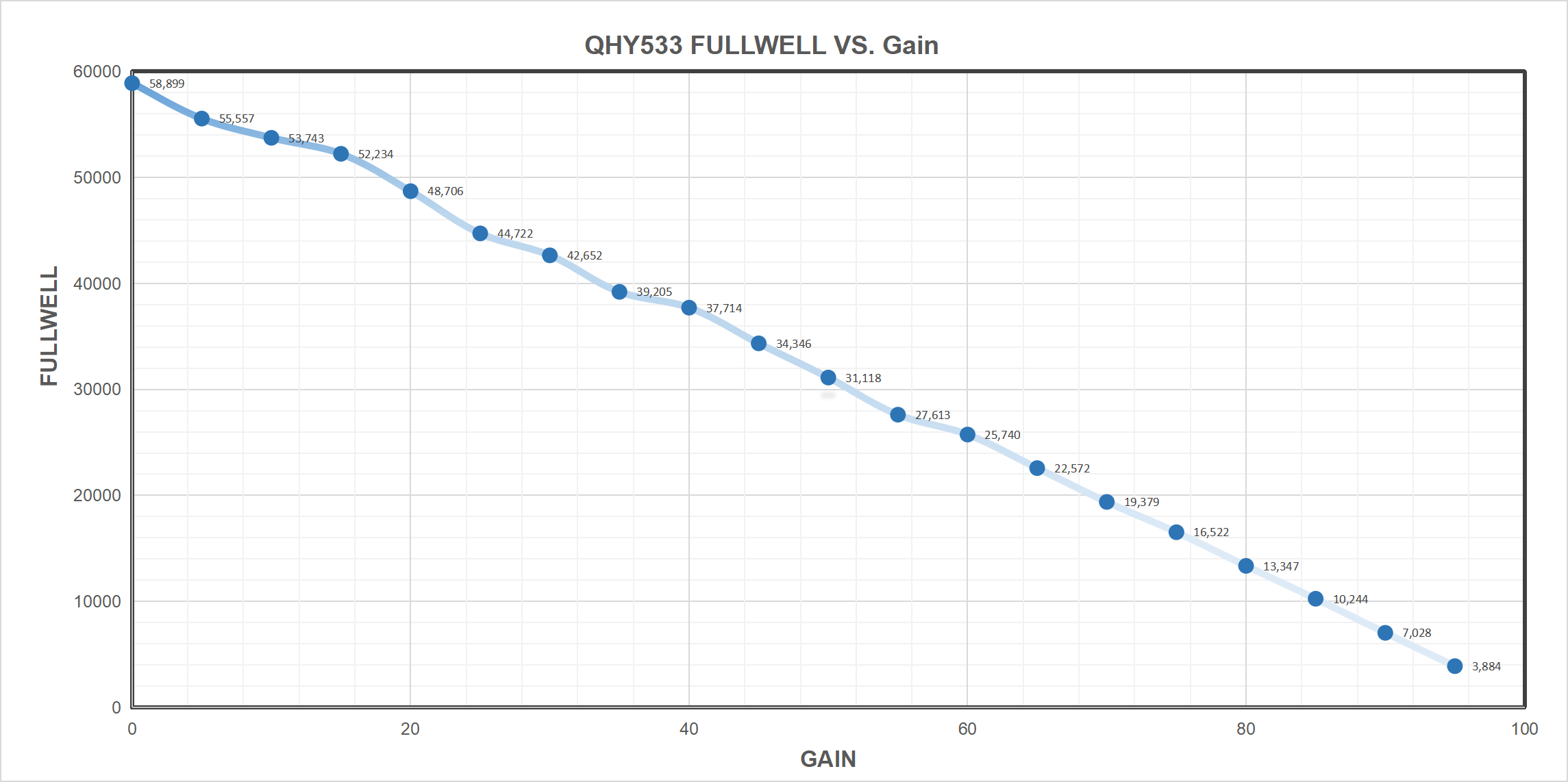
| Full Well Capacity (1×1, 2×2, 3×3) | 58ke- | |
| Full Frame Rate | USB3.0 Port: Full Resolution 26.5FPS @8BIT 20FPS @16BIT2160Lines 37FPS @8BIT 28.5FPS@16BIT1080Lines 71.5FPS @8BIT 55FPS @16BIT768Lines 97FPS @8BIT 76FPS @16BIT480Lines 152FPS @8BIT 117FPS @16BIT240Lines 280FPS @8BIT 215FPS@16BIT |
|
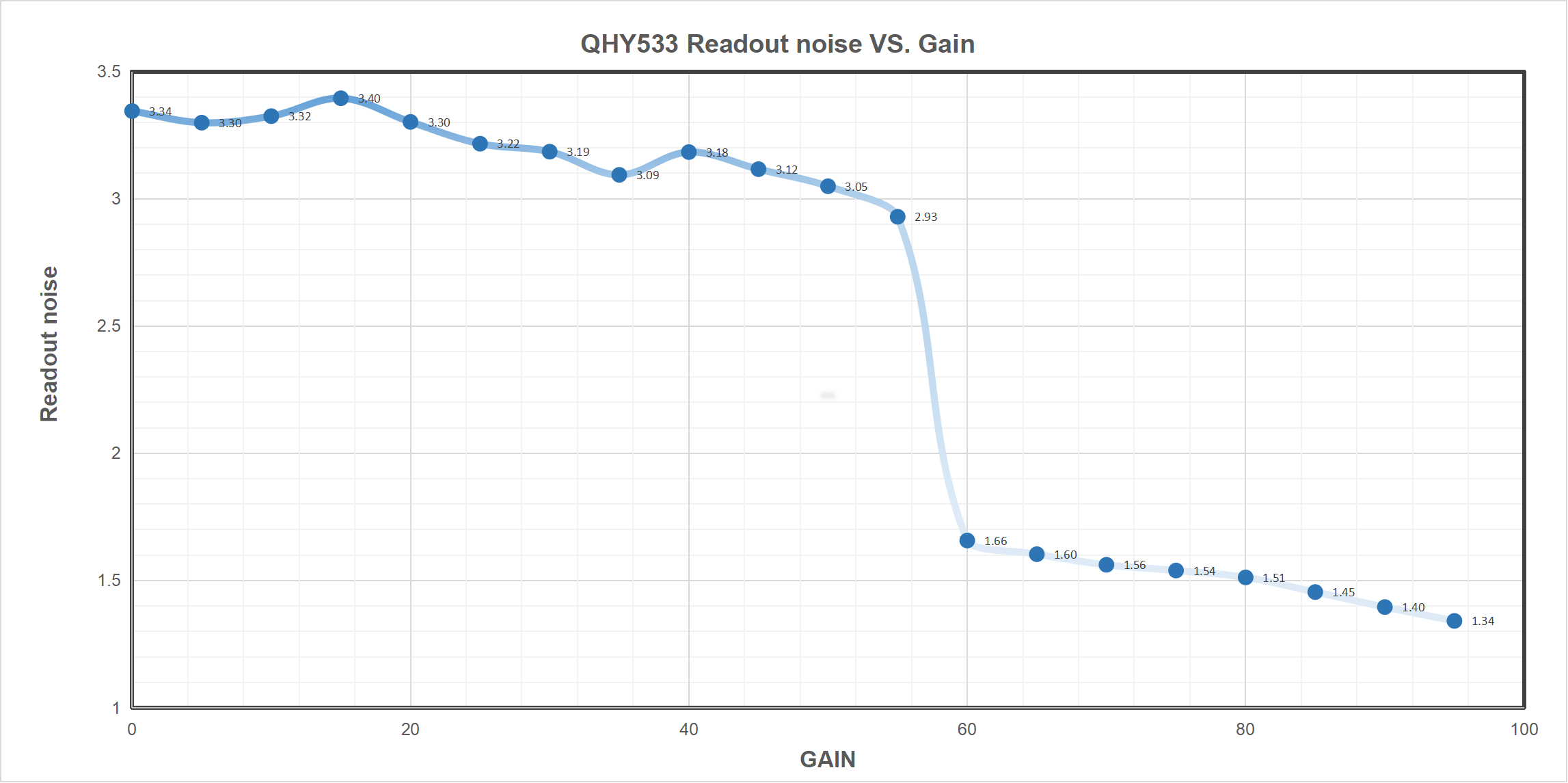
| Readout Noise | 1.3 to 3.4e- | |
| Dark Current | -20C,0.0005e- /pixel/sec | |
| Exposure Time Range | 30us-3600sec | |
| Unity Gain | 68 | |
| Shutter Type | Electronic Shutter | |
| Computer Interface | USB3.0 | |
| Built-in Image Buffer | 1GByte DDR3 Memory | |
| Cooling System | Two-stage TEC cooler
Less than 1S lower than ambient temperature -30C in continuous mode More than 1S continuous mode or lower than ambient temperature -35C in single frame mode (Test temperature +20°) |
|
| Optic Window Type | AR+AR High Quality Multi-Layer Anti-Reflection Coating | |
| Anti-Dew Heater | Yes | |
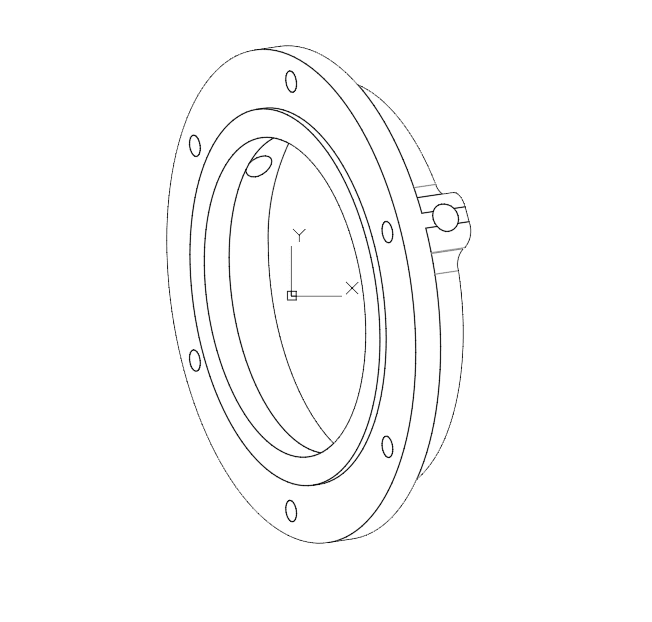
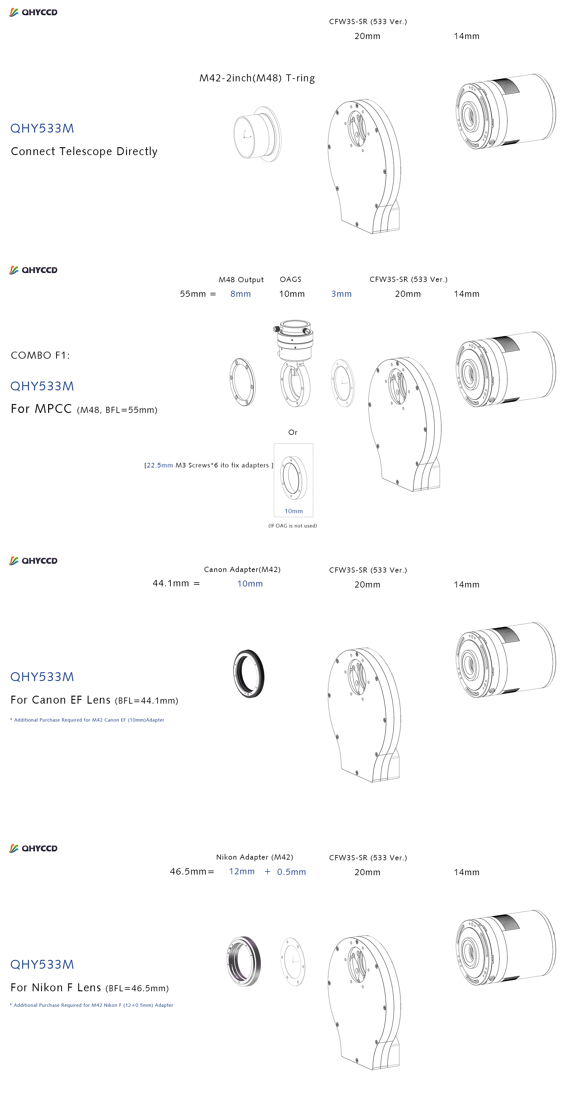
| Telescope Interface | – | Support M48 (with adapter) |
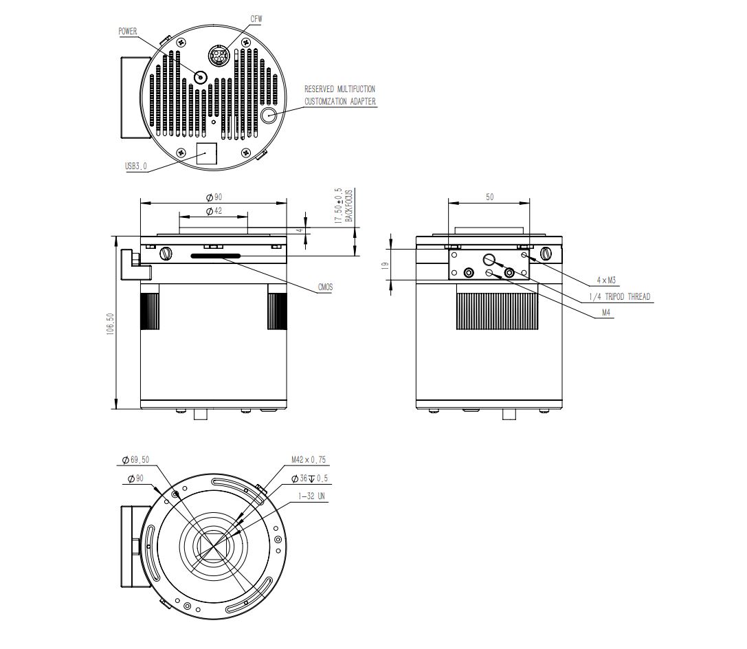
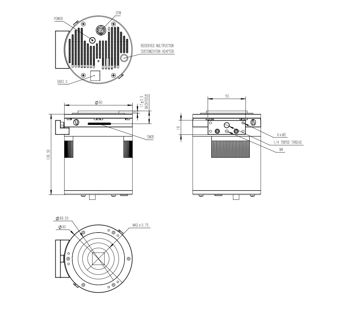
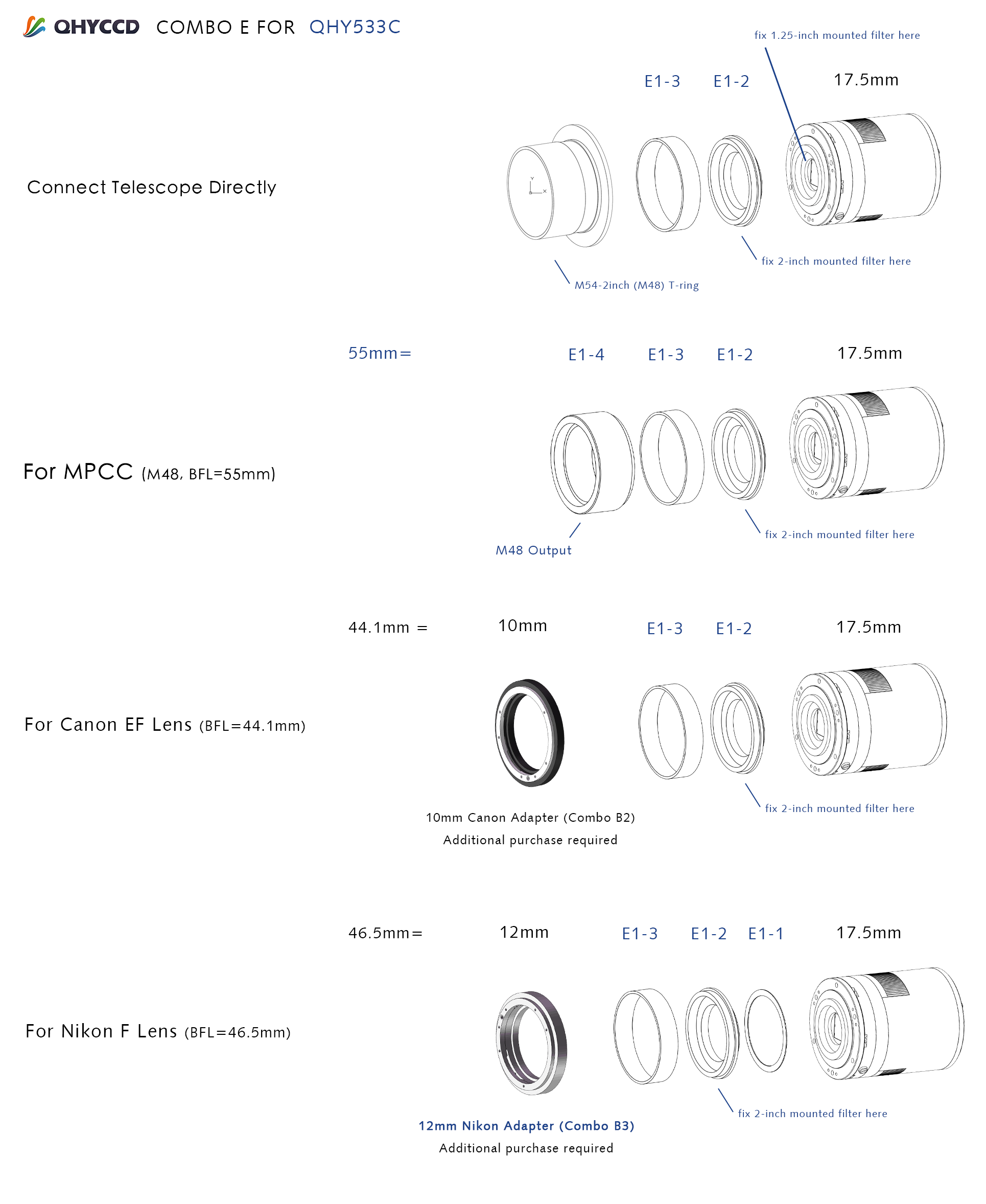
| Back Focal Length | Actual Back Focal Consumed: 14 mm (Combined with CFW)
Standard BFL: 17.5mm(±0.5) |
17mm |
| Weight | 845g | 845g |
Note: Now only QHY600, QHY268, QHY410, QHY411, QHY461, QHY533 cameras have UVLO function.
What is UVLO?
UVLO(Under Voltage Locking), is primarily intended to protect the electronic device from damage caused by abnormally low voltages.
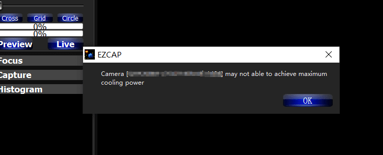
Our daily life experience tells us that the actual operational voltage of an electrical device must not significantly exceed the rated voltage, otherwise it will be damaged. For such precision equipment as cameras, long-term work at too low input voltage can also be detrimental to the working life of the camera, and may even make some devices, such as power manager, burn up due to long-term overload. In the all-in-one driver and SDK after 2021.10.23 stable version, the camera will give a warning when the input voltage of the camera is below 11V.
UVLO warning execution
After a warning is given, the camera firmware will automatically turn off the cooler and will turn on the camera’s TEC protection mode. After the camera is reconnected, it will always work in TEC protection mode (maximum power cooler power will be limited to 70%). Since many times the voltage shortage is caused by the high resistance of the power supply cable itself, resulting in a large voltage drop at high currents, the voltage will usually rise after the power is limited. But limiting the power will affect the cooling temperature difference. Therefore, it is recommended that users first check the power supply cable to solve the problem of excessive resistance of the power supply cable.
If the user has solved the problem of insufficient supply voltage, the TEC protection mode can be removed through the menu of EZCAP_QT.
How to improve the power supply?
- Make sure the output voltage of the AC adapter is not less than 12V and the maximum output current can reach 4A or more. Otherwise, the AC adapter itself will not meet the power demand of the camera and it may cause a low voltage problem.
- Make sure that the 12V power supply cable connecting the AC adapter to the camera has a low impedance. The impedance of the positive and negative paths should not exceed 0.1 ohms each. Or the total impedance (positive + negative) should not exceed 0.2 ohms. Otherwise, the power supply cable should be thickened.
- When using battery power, it is recommended to add a 12V output voltage regulator. If the battery is connected directly, usually the battery voltage reaches 13.8V when fully charged, and will gradually drop during use. It is easy to cause the camera to reach the low-voltage detection threshold.
How to clear the TEC protection status triggered by UVLO?
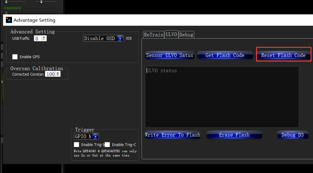
Once a UVLO event occurs, the camera will automatically memorize it and will work in a protected mode at a maximum of 70% power after reconnection. This memory can be erased as follows:
After you find the system error, you need to turn off the device and check the power supply. After inspecting the problem, open the ezcap software and select “Camera Settings” – “Preferences” – “Reset Flash Code” to reset the error status.
Why does the warning appear even though the power supply voltage is 12 V?
- The voltage measured inside the camera is the voltage reaching the camera, not the voltage at the power adapter end. Therefore, the voltage measured at the power adapter end does not reflect the voltage received at the camera end. This is because the power cable has its own resistance. If the resistance is large, it will cause a large voltage drop. The voltage drop can be calculated by U = I * R. So if the power cable has a resistance of 0.2 ohms, it will produce a voltage drop of 3.3 * 0.2 = 0.66V. If the power adapter output is 12 V, the voltage reaching the camera is 12 – 0.66 = 11.34 V. To actually measure the input voltage at the camera end, you can refer to the photo below.
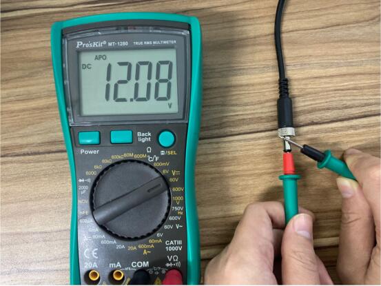
- For cameras produced after September 2021, the UVLO is detected by communicating directly with the power manager, and the UVLO code that appears is 9, while for cameras produced before, the indirect detection method is used, and the UVLO code that appears is 3. The indirect detection method will detect UVLO except for the low voltage problem, and any other accident that causes CMOS not to work will also trigger the UVLO=3 alarm, for example, the camera is subject to severe electromagnetic interference, causing registers inside the CMOS not to work. Therefore, if UVLO=3 occurs, it is recommended to contact QHYCCD technical support for further judgment.
- Using older versions of drivers and firmware may cause false positives (UVLO=9). Please make sure that ALL-in-one SDK version is out of stable version 2021.10.23 or higher. Please disconnect the 12V power supply during the driver installation.


