QHYCCD QHY294M+CFW3M_US
| Availability: | More on the Way to us |
The new QHY294 Pro is a 4/3-inch back-illuminated camera, equipped with Sony IMX294 (Color) and IMX 492 (Mono) sensor. The 294 Pro has 11.7 MP at 4.63um, 14-bits A/D. The IMX294 and IMX492 chips have 46.8 million 2.315um pixels, which Sony 2×2 bins on-chip to create the sensor’s advertised 11.7 million 4.63um pixel array. The QHY294 Pro series camera is capable of locking and unlocking the on-chip binning to provide two readout modes. The first mode reads the sensor “locked” mode to produce 11.6mp images with 4.63um pixel size and 14 bits per pixel. The second read mode unlocks the binning to produce 46.8mp images with 2.315um pixel size at 12 bits per pixel.
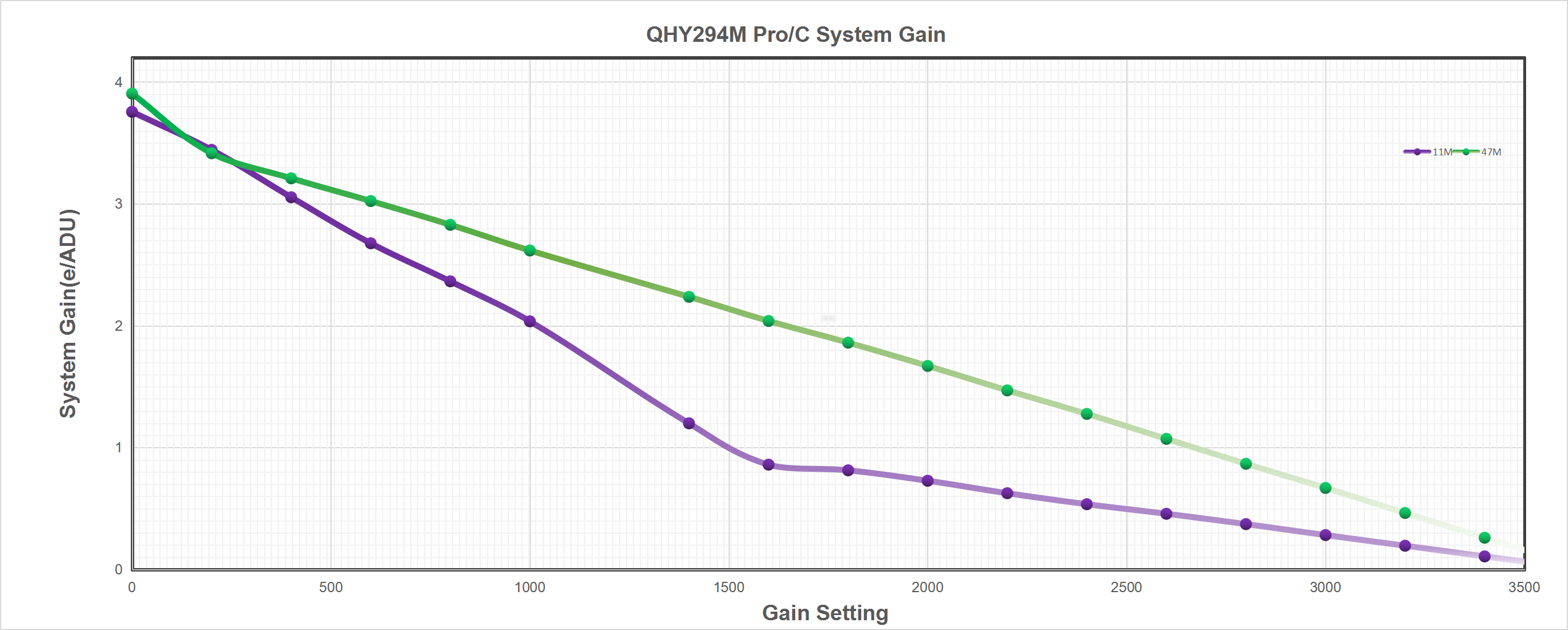
The QHY294 Pro CMOS sensor has a dual gain mode, HGC (high gain) and LGC (Low gain). The QHY294 Pro will switch the two modes automatically when the gain is set to 1600 you will get the benefits of the ultra low read noise (1e- to 1.6e-) of the HGC mode and a full well capacity of about 14.5ke- at the switch point setting.
One benefit of the back-illuminated CMOS structure is improved full well capacity. In a typical front-illuminated sensor, photons from the target entering the photosensitive layer of the sensor must first pass through the metal wiring that is embedded just above the photosensitive layer. The wiring structure reflects some of the photons and reduces the efficiency of the sensor.
In the back- illuminated sensor the light is allowed to enter the photosensitive surface from the reverse side. In this case the sensor’s embedded wiring structure is below the photosensitive layer. As a result, more incoming photons strike the photosensitive layer and more electrons are generated and captured in the pixel well. This ratio of photon to electron production is called quantum efficiency. The higher the quantum efficiency the more efficient the sensor is at converting photons to electrons and hence the more sensitive the sensor is to capturing an image of something dim.
In the DSLR implementation there is a RAW image output, but typically it is not completely RAW. Some evidence of noise reduction and hot pixel removal is still visible on close inspection. This can have a negative effect on the image for astronomy such as the “star eater” effect. However, QHY Cameras offer TRUE RAW IMAGE OUTPUT and produces an image comprised of the original signal only, thereby maintaining the maximum flexibility for post-acquisition astronomical image processing programs and other scientific imaging applications.
Based on almost 20-year cooled camera design experience, The QHY cooled camera has implemented the fully dew control solutions. The optic window has built-in dew heater and the chamber is protected from internal humidity condensation. An electric heating board for the chamber window can prevent the formation of dew and the sensor itself is kept dry with our silicon gel tube socket design for control of humidity within the sensor chamber.
Cooling
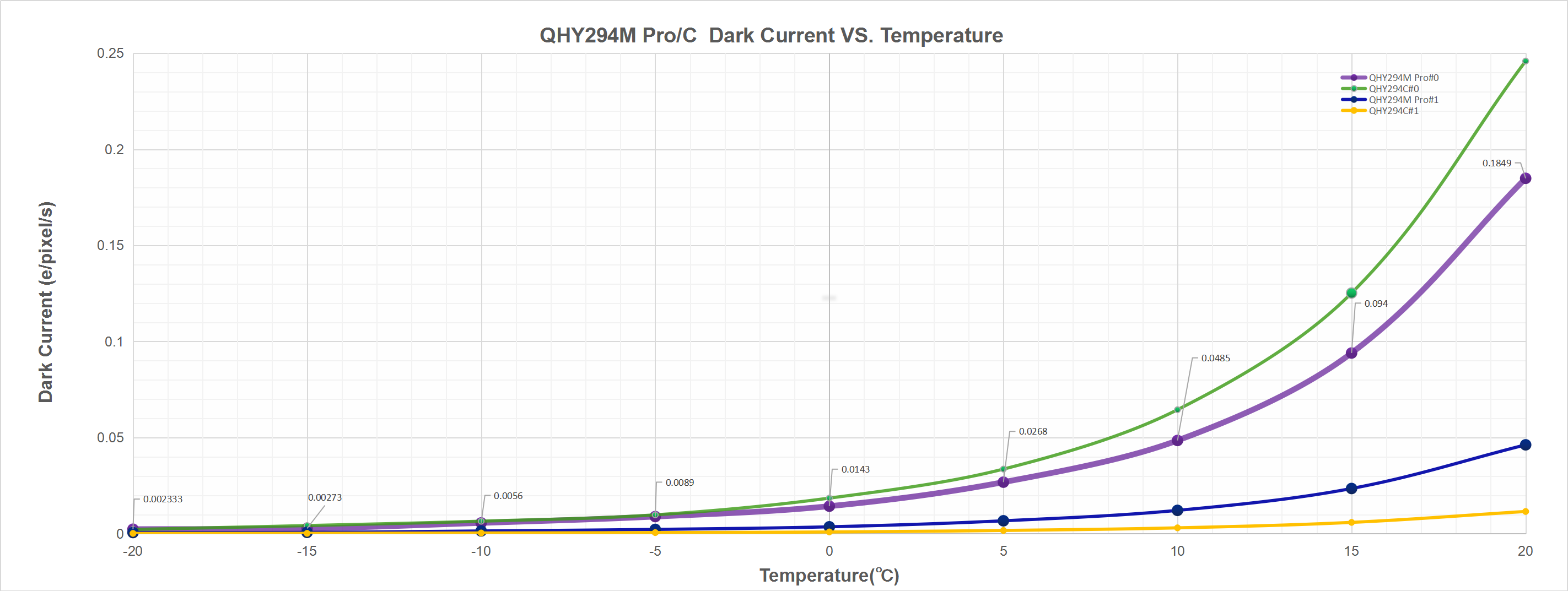
In addition to dual stage TE cooling, QHYCCD implements proprietary technology in hardware to control the dark current noise.
| Model | QHY294M Pro QHY294C Pro |
| COMS Sensor | SONY IMX492 (MONO) SONY IMX294(COLOR) |
| Mono/Color | Both |
| FSI/BSI | BSI |
| Pixel Size | 4.63um*4.63um |
| Effective Pixel Area | 4164*2796 |
| Effective Pixels | 11.7MP
46.8MP(Extended Pixel Mode) |
| Sensor Size | 4/3 inch
19.28mm*12.95mm |
| AD Sample Depth
|
14bit |
| Fullwell | 65ke- |
| Full Frame Rate | Standard 11.6mega pixel mode
4164*2796 16.5FPS@14BIT 2160lines(eg.4164*2160,4096*2160) 21FPS 1080lines(eg.4164*2160,1920*2160) 41FPS 960lines(eg.4164*960,1280*960) 46FPS 768lines(eg.4164*768,1024*768) 56FPS 480lines(eg.4164*480,640*480) 87FPS 240lines(eg.4164*240,320*240) 156FPS 100lines(eg.4164*100,240*100) 290FPS
“Unlock” 47mega pixel mode 8340*5644 4FPS@14BIT and 8BIT
*Note:QHYCCD has optimized the cmos drive freqency and limit the max frame rate. The CMOS sensor may not work under the maxium frequency to ensure the better noise performance. If you need the customized higher frame rate version please contact QHYCCD. |
| Readout Noise | 1.6-1.2e- High gain mode
6.9-5.2e- Low gain mode |
| Dark Current | 0.002e/pixel/sec @-20C 0.005e/pixel/sec @-10C |
| Exposure Time Range | 60us-3600sec |
| Unity Gain | 1600 (11MP Mode)
2600 (47MP Mode) |
| Hardware Anti-Glow Reduction | Yes. Can reduce the amp glow of the sensor in long exposure. |
| Shutter Type | Electric Rolling Shutter |
| Computer Interface | USB3.0 |
| Built-in Image Buffer | 256Mbyte DDR3 Memory |
| Cooling System | Dual Stage TEC cooler(about -35C below ambient) |
| Optic Window Type | AR+AR High Quality Multi-Layer Anti-Reflection Coating (For color camera user need to add a UV/IR filter in the light path) |
| Anti-Dew Heater | Yes |
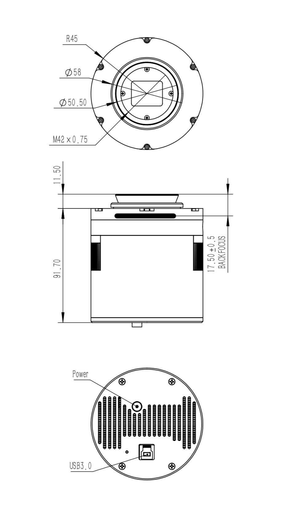
| Telescope Interface | M42/0.75 |
| Back Focal Length | 17.5mm |
| Weigth | 650g |
【User Interview】Justin P‘s Astrophotography Story
【User Interview】Amit Kamble’s Astrophotography Story
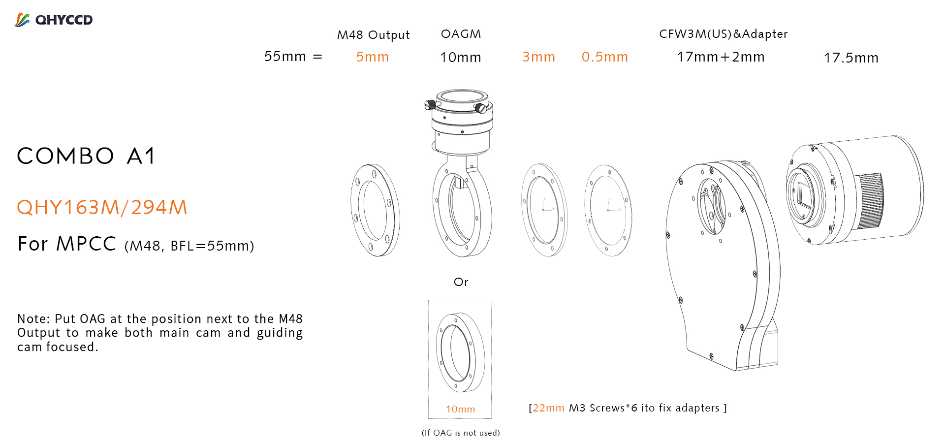
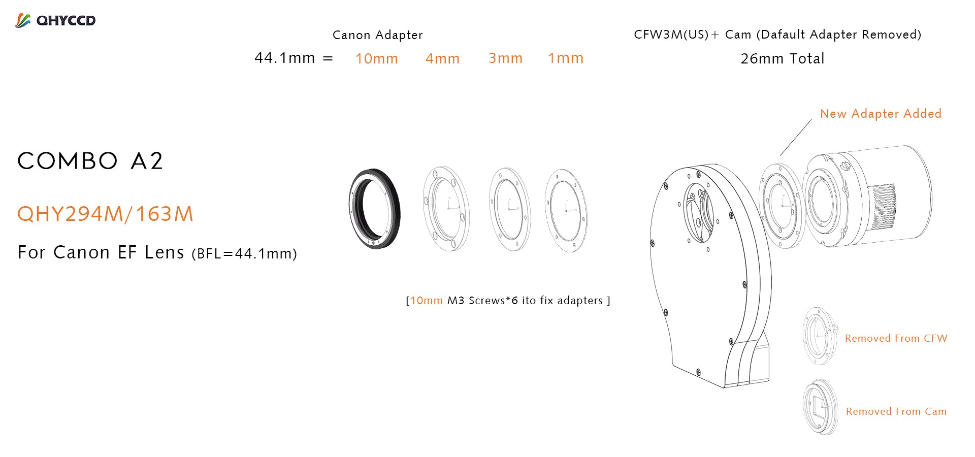
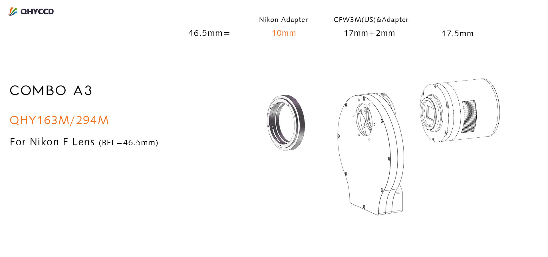
For cameras with a sensor larger than 1-inch and smaller than APS-C (QHY163m/294m) we recommend a combination of CFW3M (US) + OAGM (optional);
| Model | BFL Consumed | Filters Supported |
| QHY163M/294M | 17.5mm | 7 position
36mm unmounted |
| CFW3M-US | 17.5mm | |
| OAGM | 10mm |
Back Focal Length (BFL), in the commercial camera field, refers to the design distance from the center of the rear lens element to the surface of the sensor. Generally, the lens will only focus correctly at infinity if the camera’s back focal length meets the standard requirements provided by the lens manufacturer. This is also true for many Multi-Purpose Coma Correctors designed to be used on telescopes before the camera.
| Optical system | Back focal length required |
| Typical Multi-Purpose Coma Corrector | 55mm – 57.5mm |
| Canon 35mm lens | 44.1mm |
| Nikon 35mm lens | 46.5mm |
Note:
- If you only own CFW3M-SR whose BFL is 20.5mm rather than 17.5mm, this adapter combination can still be used, just remove the 3mm and 0.5mm adapters.
- If your MPCC requires a BFL different from 55mm, this adjustment can be made by selecting the appropriate spacer between the MPCC and the OAG. For example, an MPCC that requires 57.5mm can be used instead by adding a spacer ring or rings that add 2.5mm of BFL. to the diagram above.
- If you don’t use an OAG, you can use a 10mm spacer adapter in the adapter kits to replace the original position of OAG.
- Put OAG at the position next to the M48 Output to make both main cam and guiding cam focused.


