Peterson Engineering Eye Opener III 2 Inch Visual Back
| Article number: | PE-EOIII |
| Availability: | More on the Way to us |
| Delivery time: | More on the Way to us |
The EyeOpener 2-inch Visual Back
- Increase light reaching your eye or camera chip by as much as 65%
- It’s the equivalent of buying the next size bigger scope.
- Fits all Meade 10″, 12″ and 14″ SCTs
Visual observer? 2″ eyepieces are “where it’s at” for the widest and brightest field of view. The EyeOpener enhances the performance of 2″ eyepieces on Meade 10”, 12″ and 14” SCTs by increasing the optical path size from 1 ½” to 2″.
Imaging? With all but the smallest (oldest) chips, all SCT camera setups suffer from vignetting (darkness at the corners of the image). Increasing your scope’s optical path from 1 ½” to 2″ in diameter is almost mandatory for today’s imagers.
History: As Schmidt-Cassegrain Telescopes (SCTs) evolved from 8-inch models to larger-aperture scopes, and as eyepieces evolved from 1 ¼” to 2″, the “Schmidt-thread” couplings used for securing 1¼ inch diagonals and eyepieces to telescope backplates remained unchanged. This “Schmidt visual back” supplied with Meade (and Celestron) SCTs has an internal diameter of 1 ½”, and it functions as a 1 ½” inch-diameter field stop. This field stop effectively limits the performance of modern 2″ optics to the equivalent of 1 ½” optics. When using the 1 ½” visual back with Meade’s 2″ 56mm Plossel (an eyepiece with a full 2″ of glass in the nose) you lose 65% of the light to your eye! For imagers, the same holds true for your camera chip.
The EyeOpener will not improve your viewing with 1-1/4″ eyepieces or with the smaller 2″ eyepieces. But it is hugely beneficial when used with the larger 2″ eyepieces that give you your widest actual field of view.
For a technical explanation of vignetting and how the EyeOpener makes viewing brighter and images both larger and brighter press button.
Vignetting Explanation with Ray Diagrams
DOC G’s RAY TRACE ANALYSIS IS A FAIRLY TECHNICAL EXPLANATION OF VIGNETTING. BUT THE BENEFITS OF REDUCING ANY OBSTRUCTION IN THE OPTICAL PATH ARE OBVIOUS, BE IT FOR VISUAL OBSERVING OR IMAGING.
Vignetting Caused by the Limiting Aperture of Various Tubes and Adapters
“Doc G” aka Richard Greiner PhD
An SCT telescope has a very complex baffling system. This is necessary to prevent light from the corrector plate from leaking directly through to the image focal plane. Such leakage would cause the image, which is a real aerial image, to be diluted and lowered in contrast. Unfortunately the geometry and mirror placement in a folded optical system is so restricted that these baffles also cut off some of the rays that should form the image a distance off of the optical axis. The image is brightest on axis, at the center of the field of view, and dimmer off axis. This is a classic case of vignetting. Note that this is not a sharp cut off of the image, but a gradual dimming of it. Unfortunately, it is a feature of folded telescope optics which cannot be avoided. It is thus important to not exacerbate the vignetting by restricting the image forming rays additionally with connecting tubes which are of insufficient size at the output end of the telescope. Unfortunately, all too many adapters added to the back of an SCT do just that. This is partly the result of a decision made many years ago to use an output thread onto which most adapters are fitted. When amateur SCT instruments were first designed they were often 4 inch or 8 inch optical assemblies. Thus their output light beam was only slightly over an inch in diameter. The typical eyepiece was a 1 1/4 inch (32 mm). This so called Schmidt adapter thread and its associated tube has a typical diameter of 38 mm. This is adequate for a 1 1/4 inch (32 mm) eyepiece. In the intervening years the SCT became very popular and was made in sizes of 10, 12, 14 and even 16 inches. Such telescopes can have and indeed often do have much larger beams of light that are useful for image formation. Most current SCT instruments have a full 2 inch (50) and some even a 3 inch (75 mm) diameter circle of full illumination. Thus the early standard output adapter is significantly too small in diameter for the newer larger telescopes. It both limits the size of the actual field of view of the telescope and vignettes the light beam reaching the image focal plane.
First consider the cone of illumination of the raw telescope system as shown in Illustration 0. Here we see what is apparently a satisfactory illumination system. In fact, If you hold a piece of transparent paper behind the telescope with it pointing at a bright flat surface at some distance, you will see and ever increasing circle of illumination as you move the paper back away from the telescope. Unfortunately, this is a serious illusion for several reasons. As the illustration shows, only the central region of the cone of illumination is fully illuminated. The regions outside of A and B is only illuminated by some of the rays that transit the tube.
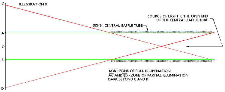
The illumination falls off to zero at points C and D. At an intermediate point between A and C or B and D the illumination may be reduced by a magnitude or more. Another problem is that when doing the transparent paper experiment, it is not only possible but likely that light rays directly from the corrector plate are entering the baffle tube and striking the sheet of paper. This light is totally undesirable since it adds background flare to the entire image. It is not appropriate to do this experiment in bright light since the eye is not as sensitive to intensity variations at high light levels as it is a very low light levels. At first it looks like there should be no trouble illuminating a 2 inch eyepiece. But, the above situation is greatly modified by the typical back plate on the telescope.
The above problems are indicative of the difficulty in baffling a folded optical system. The baffle tube has to be made big enough to accept the light from the secondary mirror, but not so big as to allow rays to pass directly from the corrector plate. This is a tough mechanical design problem and is the source of some vignetting in an even well designed folded optical system.
The vignetting phenomenon is described below in some detail for several common optical setups in the following discussion. . In Illustration 1, the light coming toward the image is restricted only by the central baffle tube. This tube is shown for illustration to be 2 inches in diameter. Only in larger SCT instruments will the central tube be as large as 2 inches. In the SCT, this tube is the central structure that holds the primary mirror. The light is directed to the left from the secondary mirror (not shown). Notice that when all tubing is of at least the same size as the baffle tube, as shown, all of the light which enters the baffle tube at the right can reach the focal plane at the left. The size of the focal plane that is well illuminated is about the same as the baffle tube. For a focal plane larger than the baffle tube size, full illumination strikes the focal plane on the optical axis of the system, but not all of the image forming light makes it to regions of the focal plane that are well off axis of the focal plane. As the diagram shows, the focal plane is vignetted for regions beyond the points A-O-B. That is, the green rays reaching point O come from the entire baffle opening at the right. Also, the red rays reaching points A and B come from the entire baffle opening. Again, the light is not cut off abruptly, but gradually fades out to darkness.

Most often when an off axis position where the light is greatly reduced is reached, the optical aberrations also are so severe that the image is poor to useless. But it can be seen that a telescope with a 2 inch diameter baffle tube (50 mm) can fully illuminate the field stop of a 2 inch eyepiece. The field stop of a long focal length 2 inch eyepiece is just a bit smaller than 2 inches. The situation shown in diagram No. 1 is ideal since the eyepiece will have a bright field over its entire apparent field because it is fully illuminated by the light beam coming down the baffle tube..
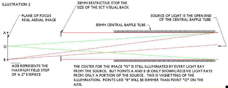
Now let us turn to the situation in diagram No. 2. Here a stop has been placed in the light path. The stop in this case is drawn to be approximately the size of the Schmidt threaded visual back commonly used on SCT telescopes. This tube has an internal diameter of 30 to 38 mm. The stop might also represent the tube used to connect a 2 inch diagonal with this thread to the back of the telescope. In this case, it is clear that the center of the image at point O can still see the entire aperture at the right end of the baffle. Thus it receives all of the light rays going down the baffle, the green rays. But as one moves off axis toward the edge of the focal plane, such as points A or B, it is clear that these points can only see a restricted portion of the aperture at the right end of the baffle tube. This is shown by the red rays. Clearly some of the rays are intercepted by the stop which is too small. Not all desired light rays can get to focal plane regions near A or B. Thus regions of the focal plane away from the optical axis are not fully illuminated. They are what is called in optical parlance vignetted. The severity of the vignetting depends on the details of the geometry of the baffle and the tubular restriction. But it is clear that any tubular opening that is smaller than the full size of the baffle tube will cause some vignetting. In the case shown, it looks like the light will be reduced by about a factor of 2 or 3. This means that the stars at the edge of the field will be about a magnitude dimmer than they should be.
So, rule number one is to use only full sized, in this case 2 inch, tubing everywhere in the optical path if vignetting is to be avoided. This problem is well recognized and a number of manufacturers make adapters which provide full illumination of a 2 inch eyepiece on a typical 10 to 16 inch SCT. Notice also that if a photographic film is to be fully illuminated, a 2 inch system is essential. The 35 mm format has a diagonal of 43 mm. A system with full 2 inch tubing will cover the film properly. Also note that with small CCD chips, where the diagonal is much smaller the problem is less severe. The chip only occupies the central region of the focal plane and is easy to fully illuminate it.
An aside to this rather obvious optical situation is that it is also wise to keep the surfaces of the tubing away from the axis of the optical system as much as possible. The reason is that if light rays strike a surface at near grazing angles they are well reflected. The use of baffles, or reflection reducing treatment is essential. Baffling is described in another article on this web site. Even the smaller 1 1/4 inch eyepieces can benefit from larger connecting hardware.
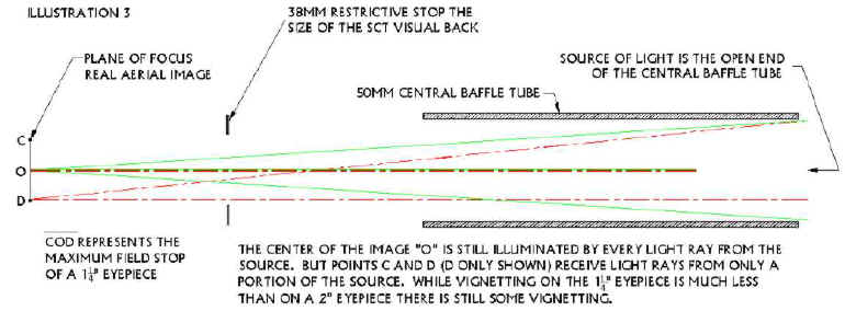
Diagram No. 3 shows the same baffle tube, but with a 1 1/4 inch (32 mm) eyepiece. It is clear here that the vignetting problem is much less severe. Again, it must be emphasized that vignetting of the illumination is not an abrupt cut off of the image. It is a gradual dimming of the image as one moves away from the optical axis.
Insertion of a Lens in the Optical Path
The question often arises about what happens when an auxiliary lens is installed in the optical path. These lenses are of two types. One is a negative lens, Barlow lens, which spreads the light beam coming down the baffle tube. This type of lens does not generally cause vignetting since it spreads the incoming light beam over a larger diameter. The negative lens can, in fact, improve the uniformity of illumination of at the focal plane. The result of using a negative lens is to create a dimmer image, but one that is more spread out. This results in a larger image and an apparent extension of the focal length of the optical system. Such lenses are often used to image planets so as to obtain a larger image. Since the planets are generally quite bright but very small compared to deep space objects, they benefit from a larger but dimmer image.
A critical and less well understood case is that which happens when a positive lens is introduced in the light beam. The positive lens is the well known focal reducer. This lens concentrates the image into a smaller circle, making it smaller, and of course concentrates the beam of light as well, making it brighter. This is a great advantage when trying to fit an extended astronomical object onto a small CCD chip. The focal reducer decreases the effective focal length of the telescope and because of the concentration of the light beam, increases the effective brightness of the image. This is a considerable advantage when trying to fit a large very dim object on a small CCD chip. With an eyepiece that has a given diameter field stop the reducer also forces more image to fall within the field stop. Thus the actual field of view of the telescope is increased with use of a focal reducer. This can be desirable for viewing where a larger actual field of view is often attractive. But because the focal reducer concentrates the beam of light coming down the baffle tube it often causes quite perceptible vignetting. This effect is shown in diagram No. 4. The original beam of light is about 2 inches in diameter as shown in the diagram. The beam of light after passing through the focal reducer will be less than that diameter. The full intensity beam might be only an inch or inch and a half instead of 2 inches in diameter. In the case shown, the beam will not fully illuminate a 2 inch field stop. A long focal length, 2 inch eyepiece has a field stop nearly 2 inches (generally about 46 mm) in diameter. There will be a severe falling off of the light in the outer parts of the field. Again note that the light is not sharply cut off, but gradually dims as one moves away from the optical axis. This dimming can easily amount to several magnitudes light reduction. This amount of reduction of the light intensity may not bother many viewers, but it is anathema to many others.
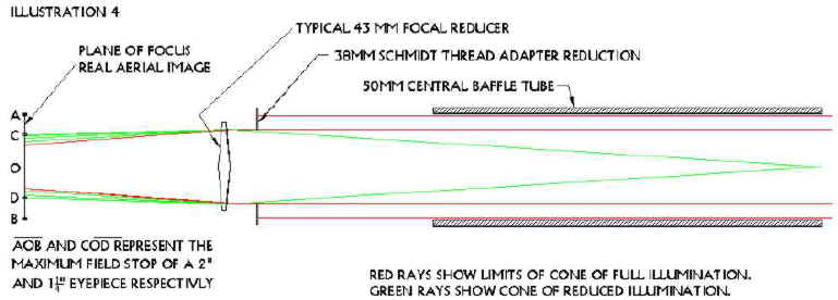
The above situation is even a bit worse than it appears at first. Focal reducers that screw onto the back of the telescope, on the Schmidt thread, have an aperture of only about 43 mm. This means that the original beam is reduced from almost 50 mm to 43 mm. It is this reduced beam which is additionally reduced by the focal reducer.
The focal reducer will generally fill the field stop of a 1 1/4 inch eyepiece. Much depends on the strength of the focal reducer. The stronger focal reducers, like a 0.33 reducer will not even fill the field stop of the smaller eyepieces. The dilemma of this situation is clear. One can, with a not too strong focal reducer get a fairly well illuminated field stop with the smaller eyepiece. This is nice in some cases. One can get a larger field of view with the larger 2 inch eyepiece, but the image will be vignetted with the focal reducer in place. Still the larger field of view obtainable with the 2 inch eyepiece is often desirable even if the illumination is not perfectly uniform over the whole apparent field of view. A 0.63 strength focal reducer will often give a nice looking wider field despite some modest vignetting.
The best way to get the biggest actual field of view, with excellent illumination, is to use an eyepiece with a full 2 inch field stop and tubing with full 2 inch openings. Peterson Engineering’s EyeOpener is specifically designed for this purpose. However, it is also useful to use a modest strength focal reducer, say 0.63, to get a bit more actual field of view with a 2 inch eyepiece of long focal length. The situation is quite different for a refractor, where there is not a restrictive baffle such as that used in the folded telescope.
The amount of vignetting one gets depends on the exact optical geometry and strength of the focal reducer. But in general, a telescope that will just fully illuminate the field stop of a 2 inch eyepiece will not do so with a focal reducer in place. The stronger the focal reduction taken, the worse the vignetting will be. Focal reducers are meant to be used with a relatively small CCD chip where a smaller circle of illumination may well be satisfactory. They are not satisfactory when trying to illuminate a 35 mm film frame. In this case it often looks like the picture was taken through a port hole.
In the 2008 -2009 period Meade 14″ scopes used a redesigned baffle tube assembly that severely constriction the optical path. A subsequent late 2009 redesign reopened the optical path to a full 2″. Check out your configuration if you have a 2008-2009 era scope. This is for 14″ only.
Check for possible Meade 14" backplate restriction
The baffles in 14″ scopes manufactured prior to late 2008 reduce the maximum optical path to 1.75″ diameter. The EyeOpener will still significantly increase your light throughput by 31%
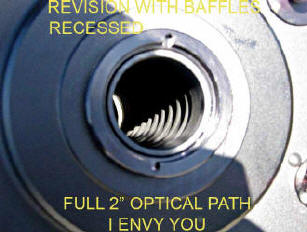
14″ Meades manufactured since late 2008 exhibit 2 different major backplate and baffle redesigns – with most opening the optical path up to a wonderfully full 2 inches and a few constricting the optical path to very restrictive 1.5 inches. Both redesigns utilize baffle tubes held in place with a spanner wrench notched ring. The thread on the outside of the ring mounts Meade’s visual back, and will also mount the EyeOpener. If you own the revision with the full 2″ optical path, congratulations. If you own the revision with the baffles restricting the ID to 1.5″, the addition of an EyeOpener will not increase the light throughput or the actual field of view of your telescope. If you have a revised 14″ measure your baffle ID to insure that the EyeOpener will benefit you.
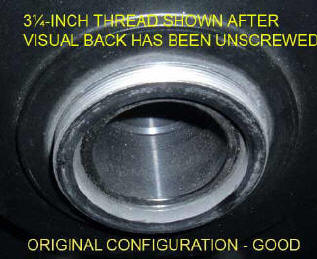
The above image shows the original 14″ backplate configuration used until 2018
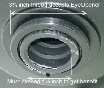
The above image shows the constrictive 14″ visual back with the 1.5″ restriction that Meade introduced in 2008. It’s believed that this variant was only produced for a shot time, but it’s best to err on the side of caution and measure your baffle tube as if you’re down to 1.5″ as shown the EyeOpener won’t help.
There are many inexpensive Schmidt thread to 2″ tube adapters being sold. They allow mounting 2-inch optics but DO NOT increase light throughput as the problem is the inside diameter of the Schmidt thread itself.
Which EyeOpener for you?
EyeOpener III
The EyeOpener directly accepts a 2″ diagonal, 2″ eyepiece, 2″ tube-end focusers and any other 2″ tube used in an optical train. It threads onto a 3-1/4″ male thread found on the backplate of 10″, 12″ and 14″ Meade SCTs. scopes, providing a full 2″ unrestricted optical path. Unscrew your 1-1/2″visual back and check it out for yourself.
The adapter is fabricated from 6061T6 aluminum and black anodized. A brass compression ring is used to prevent marring the inserted 2″ tube while griping it tightly.
The total height of the adapter above the scope’s backplate is only 1-1/2 inches (38 mm). By comparison, with the standard configuration, the nominal height from the scope’s backplate to the back of the microfocuser is 3-1/8 inches. If you need more backfocus this is a solution. With the EZ Focus kit it is possible to make the manual focuser as smooth and precise as a micrometer, pretty much eliminating the need for the microfocuser.
To mount Meade’s #1209 Zero Image-Shift electronic microfocuser you will want the EyeOpener II.


